Some circuits


Since Canvas often has trouble copying images from one shell to another, here is another set of images for some of my quizzes.
The following set of graphs were collected using the IoLab cart's wheel sensor, with the cart being given a push. The cart is on an inclined plane (ramp). It rolled up the ramp after being set in motion, and was allowed to roll back down the ramp.


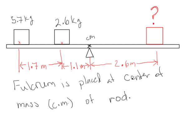
Because Canvas often fails to display images correctly in the quizzes, here is another set of images for one of my quizzes. This set is centered around the idea of using a meterstick as a balance scale.


Strictly speaking, you can't really balance the meterstick with this combination (the stick isn't long enough/you need more than 50 cm from the center of mass, which is itself at the 50 cm mark!).


Because Canvas fails to copy images and graphs from one shell to another reliably, here is another set of quiz images.


And now a couple of signs:


Here is another set of quiz images. This week's theme is resistor-inductor circuits.


A couple of circuits connected in combination.

What changed to make the response to this signal change as shown above?

Here is a signal and response with some numbers around the half-life and quarter-life decay. This is an LR circuit using a ~6.8 mH inductor with a total resistance of about 200 Ω. The sampling rate means that these times are only approximate, unfortunately. I have several more images like these, with the same stipulation concerning sampling rates.


Here I replaced the pasco resistor-capacitor-inductor circuit board with and actual inductor. The nominal inductance is 63 mH, which is about an order of magnitude larger. Again, I kept the total resistance (internal for inductor + additional resistor box) to about 100 Ω. I should probably mention that for all of these, the voltage probe is looking only at the voltage drop across the added resistor.


These two are for the same solenoid, but I have increased the total resistance (internal + added resistor) to 200Ω. I placed them here side-by side (or above and below) so that you can get a sense of the uncertainty in measurement: these are the same signal trace, I just moved the cursors to their nearest-neighbor positions.
Because Canvas doesn't always copy over images correctly, here is another set of images used for one of my quizzes.


An now, another series of QUIZ IMAGES, this time of DC circuit diagrams consisting of a variety of resistors in combination.

