Here is another set of quiz images. This week's theme is resistor-inductor circuits.
A couple of circuits connected in combination.
What changed to make the response to this signal change as shown above?
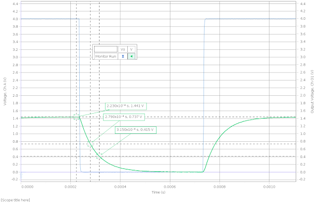
Here is a signal and response with some numbers around the half-life and quarter-life decay. This is an LR circuit using a ~6.8 mH inductor with a total resistance of about 200 Ω. The sampling rate means that these times are only approximate, unfortunately. I have several more images like these, with the same stipulation concerning sampling rates.
Here I replaced the pasco resistor-capacitor-inductor circuit board with and actual inductor. The nominal inductance is 63 mH, which is about an order of magnitude larger. Again, I kept the total resistance (internal for inductor + additional resistor box) to about 100 Ω. I should probably mention that for all of these, the voltage probe is looking only at the voltage drop across the added resistor.
These two are for the same solenoid, but I have increased the total resistance (internal + added resistor) to 200Ω. I placed them here side-by side (or above and below) so that you can get a sense of the uncertainty in measurement: these are the same signal trace, I just moved the cursors to their nearest-neighbor positions.


